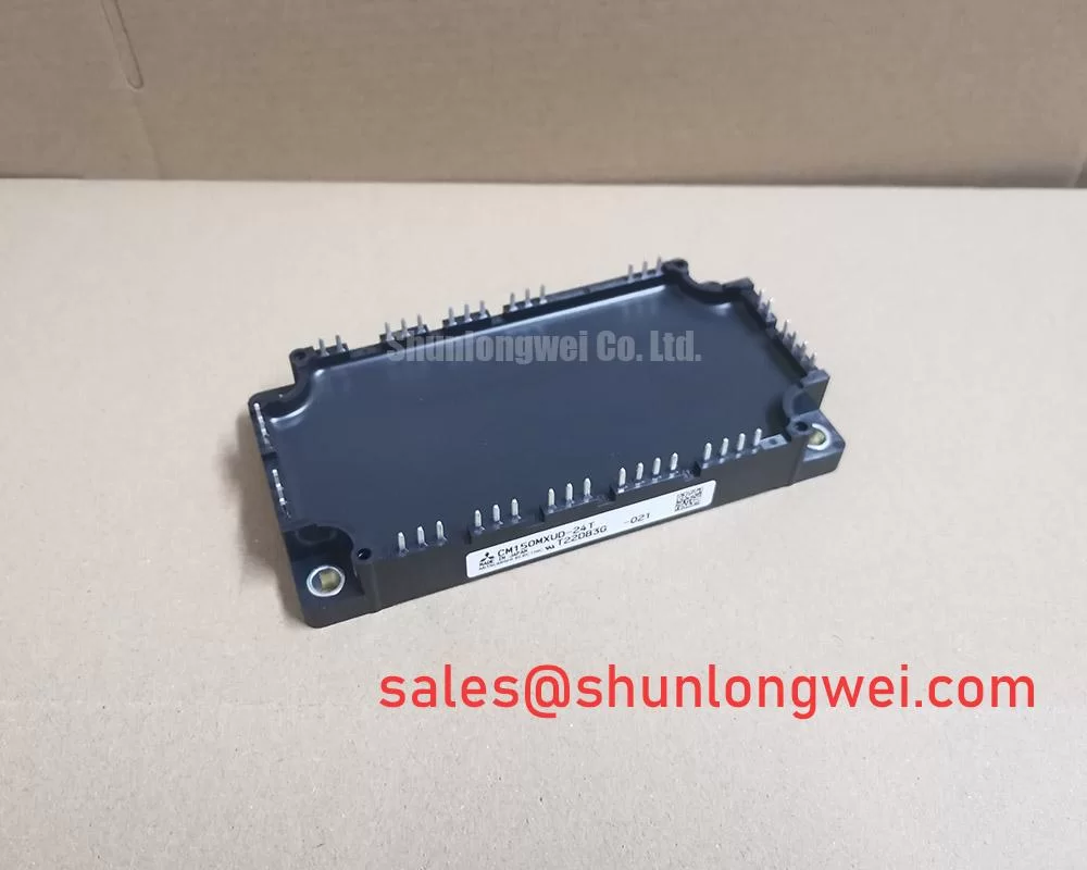
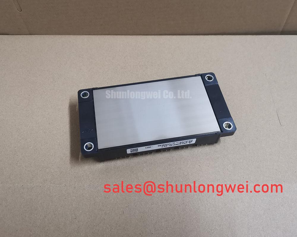
Mitsubishi #CM150MXUD-24T New Instock

Collector current IC ………….…………………… 1 5 0 A
Collector-emitter voltage VCES ……………… 1 2 0 0 V
Maximum junction temperature Tv j max ……… 1 7 5 °C
●dual switch (half-bridge)
●Nickel-plating tab terminals
●RoHS Directive compliant
APPLICATION
AC Motor Control, Motion/Servo Control, Power supply, etc.
OPTION (Below options are available.)
●PC-TIM (Phase Change Thermal Interface Material) pre-apply (Note8)
Maximum ratings and characteristics
.Absolute maximum ratings (Tc=25°C unless without specified)
VCES Collector-emitter voltage G-E short-circuited 1200 V
VGES Gate-emitter voltage C-E short-circuited ± 20 V
IC Collector current DC, TC=145 °C* (Note2, 4) 150A
ICRM Pulse, Repetitive (Note3) 300 A
Pt ot Total power dissipation TC=25 °C (Note2, 4) 1610 W
Vi s o l Isolation voltage Terminals to base plate, RMS, f=60 Hz, AC 1 min 4000 V
Tv j m a x Maximum junction temperature Instantaneous event (overload) (Note8) 175 °C
T C m a x Maximum case temperature (Note4,8) 150°C
Tv j o p Operating junction temperature Continuous operation (under switching) (Note8) -40 ~ +150°C
Ts t g Storage temperature – -40 ~ +150°C
ELECTRICAL CHARACTERISTICS (Tv j=25 °C, unless otherwise specified)
ICES Collector-emitter cut-off current VCE=VCES, G-E short-circuited – – 1.0 mA
IGES Gate-emitter leakage current VGE=VGES, C-E short-circuited – – 0.5 μA
VGE(th) Gate-emitter threshold voltage IC=15 mA, VCE=10 V 5.4 ~ 6.6 V
t r r (Note1) Reverse recovery time VCC=600 V, IE=150 A, VGE=±15 V, 400 ns
Qr r (Note1) Reverse recovery charge RG=0 Ω, Inductive load – 15 – μC
Eon Turn-on switching energy per pulse VCC=600 V, IC=IE=150 A, 11.6 mJ
Eoff Turn-off switching energy per pulse VGE=±15 V, RG=0 Ω, Tv j=150 °C, 15.7
Err (Note1) Reverse recovery energy per pulse Inductive load 6.8 mJ
RCC’+EE’ Internal lead resistance Main terminals-chip, per switch, TC=25 °C (Note4) 0.2 mΩ
r g Internal gate resistance Per switch 3.0 Ω
MECHANICAL CHARACTERISTICS
Mounting torque Main terminals M 5 screw 2.5 ~3.5 N·m
Mounting torque Mounting to heat sink M 6 screw 3.5 ~ 4.5 N·m
Creepage distance Terminal to terminal 18.4 mm
Creepage Terminal to base plate 21.1 mm
Clearance Terminal to terminal 9.6mm
Clearance Terminal to base plate 16.7 mm
Flatness of base plate On the centerline (Note7) ±0 ~+200 μm
The Mitsubishi CM150MXUD-24T is a power module that is used in the control and conversion of electric power. It is a type of insulated-gate bipolar transistor (IGBT) module. The “CM150MXUD” in the model number refers to the specific series of IGBT module which is characterized by its high-performance, high-reliability and high-voltage. The “24” in the model number refers to the maximum collector-emitter voltage rating of the IGBT, which is rated at 600V. The “T” in the model number refers to the type of package which is a base-plate cooled module with a built-in temperature sensor. The module’s features are suitable for high frequency switching, high current switching, and high power switching applications like Inverters, Servo drives, Uninterruptible Power Supply (UPS) systems, Welding machines and other industrial equipment. It is important to note that this module requires a proper heatsink and cooling solution to dissipate the heat generated during operation.
YouTube : https://www.youtube.com/watch?v=XJpkyu1D2C0
CM150MXUD-24T CM150MXUD-24T