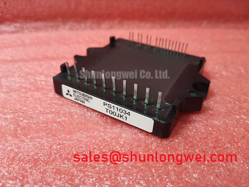
Mitsubishi PS11034 New Stock
 Sell PS11034, #Mitsubishi #PS11034 New Stock, PS11034 PS11034 FLAT-base TYPE INSULATED TYPE 450V-500V/15A-30A; PS11034, #IGBT_Module, #IGBT, #PS11034
——————————————
Email: [email protected]
——————————————-
PS11034
INTEGRATED FUNCTIONS AND FEATURES
• Converter bridge for 3 phase AC-to-DC power conversion.
• 3 phase IGBT inverter bridge configured by the latest 3rd.
generation IGBT and diode technology.
• Inverter output current capability IO (Note 1):
(Note 1) : The inverter output current is assumed to be sinusoidal and the peak current value of each of the above loading cases is defined as : IOP = IO × √2, TC < 100°C
INTEGRATED DRIVE, PROTECTION AND SYSTEM CONTROL FUNCTIONS:
• P-Side IGBTs : Drive circuit, high-level-shift circuit, bootstrap circuit supply scheme for Single Control-Power-Source drive, and under voltage (UV) protection.
• N-Side IGBTs : Drive circuit, DC-Link current sense and amplifier circuits for overcurrent protection, control-supply under-voltage
protection (UV), and fault output (FO) signaling circuit.
• Fault Output : N-side IGBT short circuit (SC), over-current (OC), and control supply under-voltage (UV).
• Inverter Analog Current Sense : N-Side IGBT DC-Link Current Sense.
• Input Interface : 5V CMOS/TTL compatible, Schmitt Trigger input, and Arm-Shoot-Through interlock protective function.
Supply voltage VCC 450V
Supply voltage (surge) VCC(surge) 500V
Each IGBT collector current ±Ic(±Icp) ±15 (±30) A
Repetitive peak reverse voltage VRRM 800V
Recommended AC input voltage Ea 220 Vrms
DC output current IO 15A
Surge (non-repetitive) forward current IFSM 150A
Supply voltage VD, VDB –0.5 ~ 20V
Input signal voltage VCIN –0.5 ~ +7.5 V
Fault output current IFO 15mA