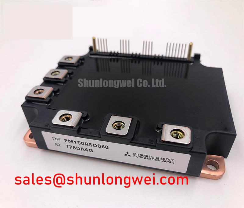
Mitsubishi PM100CSE120 New Stock
 Sell PM100CSE120, #Mitsubishi #PM100CSE120 New Stock, PM100CSE120 Powerex / Mitsubishi MadePM100CSE120 IGBT Mitsubishi 100A 1200V;, #IGBT_Module, #IGBT, #PM100CSE120
————————————————-
Email: [email protected]
————————————————–
FEATURE
a) Adopting new 4th generation planar IGBT chip, which performance is improved by 1µm fine rule process.
b) Using new Diode which is designed to get soft reverse
recovery characteristics.
•3φ 100A, 1200V Current-sense IGBT for 15kHz switching
• Monolithic gate drive & protection logic
• Detection, protection & status indication circuits for overcurrent, short-circuit, over-temperature & under-voltage
• Acoustic noise-less 18.5/22kW class inverter application
PRECAUTIONS FOR TESTING
1. Before appling any control supply voltage (VD), the input terminals should be pulled up by resistores, etc. to their corresponding supply voltage and each input signal should be kept off state.
After this, the specified ON and OFF level setting for each input signal should be done.
2. When performing “OC” and “SC” tests, the turn-off surge voltage spike at the corresponding protection operation should not
be allowed to rise above VCES rating of the device.
(These test should not be done by using a curve tracer or its equivalent.)
NOTES FOR STABLE AND SAFE OPERATION ;
•Design the PCB pattern to minimize wiring length between opto-coupler and IPM’s input terminal, and also to minimize the
stray capacity between the input and output wirings of opto-coupler.
•Quick opto-couplers : TPLH, TPLH ≤ 0.8µs. Use High CMR type. The line between opto-coupler and intelligent module
should be shortened as much as possible to minimize the floating capacitance.
•Slow switching opto-coupler : recommend to use at CTR = 100 ~ 200%, Input current = 8 ~ 10mA, to work in active.
•Use 4 isolated control power supplies (VD). Also, care should be taken to minimize the instantaneous voltage charge of the
power supply.
•Make inductance of DC bus line as small as possible, and minimize surge voltage using snubber capacitor between P and N
terminal.
•Use line noise filter capacitor (ex. 4.7nF) between each input AC line and ground to reject common-mode noise from AC line
and improve noise immunity of the system.